Previous Projects
This system has been carefully crafted to ensure that the catalyst is uniform and all parts of it experience the same experimental conditions. When the catalyst was non-uniform, however, the oscillations took the form of a non-uniform pulse which rotated around the ring.
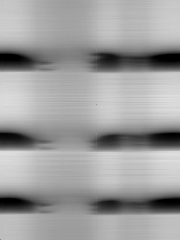
The image below shows a space-time plot of synchronized oscillations on a uniform catalyst. In this plot, the temperature of the catalyst is plotted as a function of angle (horizontal axis) and time (vertical axis) where dark colors indicate cooler regions of the catalyst. On this catalyst, the portion of the catalyst where 60° < q < 180° did not oscillate. The amplitude of the oscillations was DT = 6 °C and the period of oscillation wast = 400 s.
|
|

|
|
|
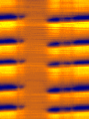
The image below shows the space-time plot for later oscillations on the same catalyst. Orange/yellow colors in the plot indicate areas where the catalyst is hot and blue represents areas where the catalyst is cool. Unlike the earlier oscillations, this behavior is not synchronized, but takes the form of a rotating pulse. The slope of the oscillations gives a propagation velocity of v = 0.8 cm/s. The pulses were much smaller and faster than the synchronized oscillations with an amplitude of DT = 0.1 °C and a period between successive pulses of t = 15 s.
|
| ||
|
|

|
|
|
|
|
For an animation of the pulse rotating around the ring, click here (586k). For best results, set your animation viewer to loop the animation.