Antimatter Technology Tools
Positron Source and Moderator
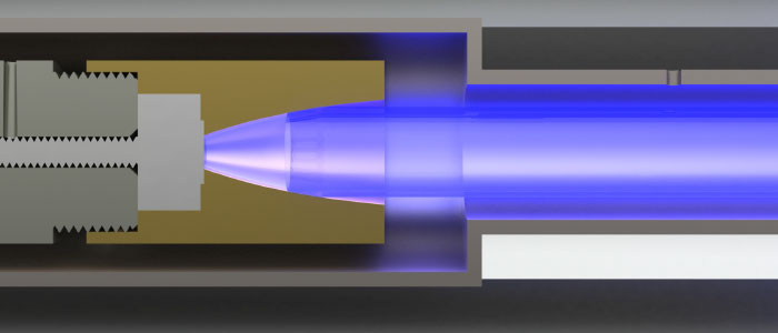
High energy positrons are emitted from a sodium-22 radioactive source. These positrons are then moderated through interactions with a neon crystal moderator, and electromagnetically guided into the buffer-gas trap (BGT) as a steady-state positron beam.
Positrons are emitted from a sodium-22 radioactive source through the process of beta plus decay, in which a proton decays into a positron, a neutron and a neutrino. These positrons are ejected with a nearly continuous range of energies between 0 and 500 keV, and so must be slowed down prior to being trapped in the buffer-gas trap (BGT). This process is called “moderation”.
A copper cone is affixed to the face of the radioactive source and cooled to 8K. Neon gas is then admitted into the source chamber where it forms a thin layer of solid neon on the cone surface. As the high energy positrons are ejected from the source they lose energy through inelastic collisions with the neon crystal, and a small fraction (~2%) are subsequently re-emitted at electron-volt energies. These moderated positrons are then guided electromagnetically towards the BGT as a steady-state positron beam which has an energy spread of approximately 2 eV FWHM.
Further Reading:
Energy distribution and adiabatic guiding of a solid-neon-moderated positron beam, S. Ghosh, et al., J. Phys. B, 53, 085701 (2020).
Solid neon moderator for positron trapping experiments, R. G. Greaves and C. M. Surko, Can. J. Phys. 51, 445 (1996).
Solid neon moderator for producing slow positrons, A. P. Mills et al., Appl. Phys. Lett. 49, 1121 (1986).
Rotating Wall
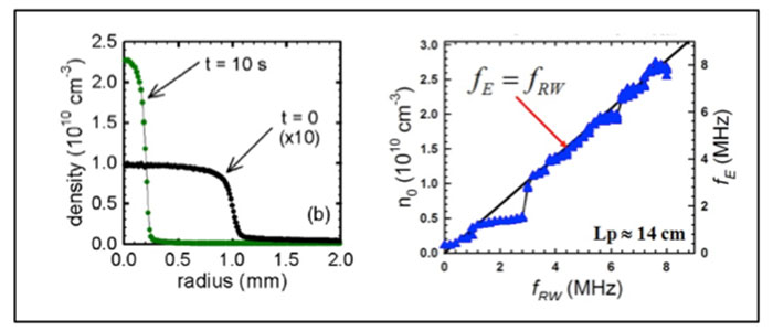
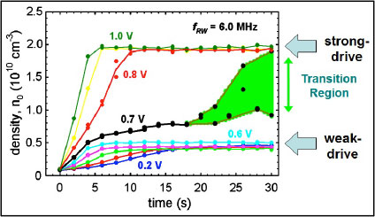
The "rotating wall technique" (RW) uses rotating electric fields to compress single component plasmas radially. Originally developed coupling to plasma modes, we discovered a "strong drive" regime in which this is unnecessary, which is a considerable simplification. This technique is now used worldwide to tailor plasmas for specific applications.
Shown above are the steady-state density for plasmas spinning up to the applied RW frequency (above right) and a comparison of the density profile before and after compression (above left). The applied RW fields and poor particle confinement cause heating, and so good cooling is required to take full advantage of this regime. In the case of cyclotron cooling, this requires several tesla magnetic fields (i.e., a high-field trap). In the panel on the right is an example of density vs. time showing the transition to the “strong-drive” regime.
The RW technique has also been used for positron gases in the single particle regime.
Further Reading:
Energy distribution and adiabatic guiding of a solid-neon-moderated positron beam, S. Ghosh, et al., J. Phys. B, 53, 085701 (2020).
"Inward Transport and Compression of a Positron Plasma by a Rotating Electric Field," Greaves et al., Phys. Rev. Lett. 85, 1883 (2000).
Torque-Balanced High-Density Steady States of Single-Component Plasmas," Danielson et al., Phys. Rev. Lett. Plasmas 94, 0305001 (2005).
Radial compression and torque-balanced steady states of single-component plasmas in Penning-Malmberg traps," Danielson et al., Phys. Plasmas 13, 055706 (2006).
Plasma manipulation techniques for positron storage in a multicell trap, Danielson et al.," Phys. Plasmas 13, 123502 (2006).
Plasma Compression using Rotating Electric Fields - the Strong Drive Regime," Danielson et al., Non-Neutral Plasma Physics VI, AIP Conf Proc. 862, 19 (2006).
Plasma and trap-based techniques for science with positrons," Danielson et al., Rev. Mod. Phys. 87, 247 (2015).
Plasma and Trap-based Techniques for Science with Antimatter, J. Fajans and C. M. Surko, Phys. Plasmas 27, 030601 (2020).
Buffer Gas Cooling
Low positron temperatures are optimal for a variety of studies. One method of obtaining cold positrons, known as buffer-gas cooling, is to allow them to interact with a molecular gas where they eventually reach the gas temperature through inelastic collisions. This technique is used in both the buffer gas trap (BGT) and cryogenic beam-tailoring trap (CBT) devices within our lab.
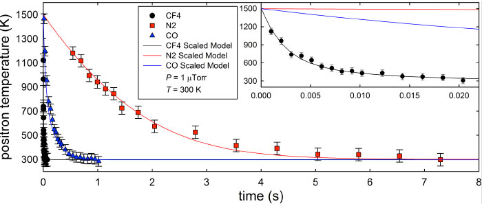
Buffer-gas cooling relies on inelastic collisions between the positons and a molecular gas. The cooling rate obtained using this technique varies widely depending on the availability and strength of the open inelastic channels of the buffer-gas used. Typically, high temperature positrons cool predominantly through electronic excitation and ionization, while at low temperatures vibrational and rotational excitations dominate.
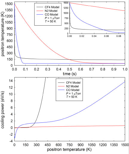
The key to rapidly cooling positrons to 300K using this technique lies in using a buffer-gas with a strong vibrational excitation cross-section. This is the reason CF4 cools significantly more rapidly than either CO or N2 in the data shown above. In contrast, cooling the positrons to much lower temperatures requires a strong rotational excitation cross-section, since vibrational cooling shuts off at higher temperatures than rotational cooling. This is seen in the figures to the right, which shows the predicted cooling for positrons interacting with 50K buffer-gases. Here it is seen that positron cooling with CF4 becomes inefficient at low temperatures, while both CO and N2 allow the positrons to reach lower temperatures due to the presence of low energy rotational excitations. For these reasons, CO appears to be the optimal buffer-gas for obtaining very low temperature positrons, due to the presence of both vibrational and rotational excitations. Using these techniques we have successfully cooled positrons to temperatures as low as 50K using either a CO or N2 cryogenic buffer-gas, which is a crucial step employed in the cryogenic beam-tailoring trap (CBT).
Further Reading:
A Buffer-Gas Trap for the NEPOMUC Positron Beam: Optimization Studies with Electrons, A Deller, et al., J. Plasma Phys. 935890501, 2023.
Positron cooling by vibrational and rotational excitation of molecular gases, M. R. Natisin, et al., J. Phys. B 47, 225209 (2014).
Positron trapping in an electrostatic well by inelastic collisions with nitrogen molecules, T. Murphy and C. Surko, Phys. Rev. A 46, 5696 (1992).
An Ultra-High Energy Resolution Cryogenic Trap-Based Positron Beam, M. Natisin et. al., Appl. Phys. Lett. 108, 024102 (2016).
Systematic Comparison of Positron and Electron Impact Ionization of the n3 vibrational mode of CF4, J. P. Marler and C. M. Surko, Phys. Rev. A 72, 062702 (2005).
Excitation of Molecular Vibrations by Positron Impact, J. Sullivan, et al., Phys. Rev. Lett. 86, 1494-1497 (2001).
Excitation of Electronic States of Ar, H2, and N2 by Positron Impact, J. P. Sullivan, et al., Phys. Rev. Lett. 87, 073201-073204 (2001).
Cyclotron Cooling
Alternative to using a buffer gas, positrons in a high magnetic field execute tight cyclotron orbits, and the resulting particle acceleration causes them to radiate. In practical units, the cooling rate is Γ = B2/4 s-1, where B is in tesla. In the absence of other heating and cooling mechanisms, the particles will come into radiatiative equilibrium with their surroundings (e. g., the electrode walls).
While typically slower than buffer-gas cooling, the great advantage of this technique is that it is compatible with UHV vacuum. It is therefore the method of choice for antihydrogen studies where it is used directly for positrons and used to cool antiprotons sympathetically with simultaneously confined electrons.
Further reading:
"Cooling of a Pure Electron Plasma by Cyclotron Radiation," T. M. O'Neil, Phys. Fluids 23, 725-731 (1980).
"Plasma and Trap-Based Techniques for Science with Positrons," J. R. Danielson, D. H. E. Dubin, R. G. Greaves, and C. M. Surko, Rev. Mod. Phys. 87, 247 (2015).
Autoresonant Diocotron-mode Control
Autoresonance refers to the phenomenon by which a nonlinear oscillator can phase-lock to a drive signal. In the late 1990’s, Fajans and collaborators demonstrated that the diocotron mode can be driven autoresonantly using a frequency-chirped pulse. We have extended this technique in order controllably position (displacement and phase) a plasma off-axis so that it can be injected into the off-axis storage cells of a multicell trap.
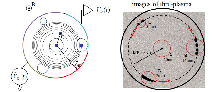
Shown at the top left is the location of the drive signal and the receive signal for an diocotron-mode autoresonance experiment, together with the spiral trajectory of the plasma resulting from a chirped-frequency drive. On the top right are images of plasmas that have been moved off-axis and passed through three off-axis storage cells.
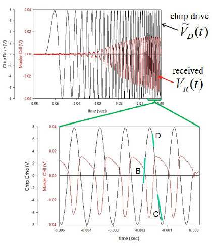
The diocotron mode frequency increases as the plasma is moved further off axis, and so if the drive frequency is increased, and this effect is used to control the plasma position using the chirped-frequency drive, while also keeping the mode phase-locked to the drive for azimuthal positioning. The top panel on the right shows the received signal along with the chirped drive, while the bottom panel shows the last few cycles, demonstrating the phase locking of the signals. Also shown are the locations of the different off-axis cells, corresponding to the cell labels shown above.
Further Reading:
Multi-cell trap developments towards the accumulation and confinement of large quantities of positrons, M. Singer, et al., J. Plasma Phys. 89, 935890501 (2023).
Autoresonant (nonstationary) excitation of the diocotron mode in non-neutral plasmas, J. Fajans et al., Phys. Rev. Lett. 82, 4444 (1999).
Confinement and manipulation of electron plasmas in a multicell trap,” N. Hurst, et al., Phys. Plasmas 26, 013513 (2019).
Electron Plasma Dynamics During Autoresonant Excitation of the Diocotron Mode, C. Baker et al., Phys. Plasmas 22, 022302 (2015).
Electron Plasma Orbits from Competing Diocotron Drifts, N. C. Hurst et al., Phys. Rev. Lett. 113, 025004 (2014).
Plasma manipulation techniques for positron storage in a multicell trap, J. Danielson et al., Phys. Plasmas 13, 123502 (2006).
Plasma Parking in Off-axis Cells
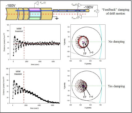
We discovered that when the plasma axially spans both the master cell and a storage cell in the multicell trap test structure, the resulting plasma drift motion is a bounce-average of the drift motions in the two regions. The resulting orbits are stable and long-lived. Consequently, they enable a number of useful manipulation techniques. The orbit can be damped to a fixed-point and then “parked” at any location in the storage cell using a separate control voltage. This procedure has enabled the successful injection of plasmas into the off-axis cells with > 95% efficiency.
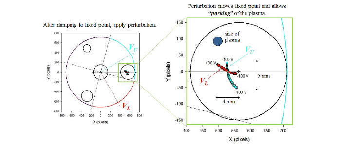
The panel at the right shows the multicell test structure with a plasma spanning both the master cell and a storage cell. Also shown are the locations of the feedback damping circuit in the storage cell region and the parking control voltage in the master-cell region. The data below shows to examples of plasma bounce-average drift orbits. In the first case, no feedback damping is applied, and the plasma maintains its orbit. In the second case (lowest panel), the feedback signal causes the orbit to damp to the fixed point (FP).
Once damped to the FP, a static control voltage is applied in the master cell; this moves the location of the FP and positions the plasma in the storage cell. Data for two different perturbation locations are shown abov). With appropriate control voltages, the plasma can be parked anywhere within ~ a 4mm x 5 mm area, with sub-mm accuracy.
After these manipulations, the plasma is “squeezed” into the off-axis cell for long-term storage.
Further reading:
Multi-cell trap developments towards the accumulation and confinement of large quantities of positrons, M. Singer, et al., J. Plasma Phys. 89, 935890501 (2023).
"Electron Plasma Orbits from Competing Diocotron Drifts," Hurst et al., Phys. Rev. Lett. 113, 025004 (2014).
"Electron Plasma Dynamics During Autoresonant Excitation of the Diocotron Mode," Baker et al., Phys. Plasmas 22, 022302 (2015).
"Plasma and trap-based techniques for science with positrons," Danielson et al., Rev. Mod. Phys. 87, 247 (2015).