Antimatter Technology Traps
Buffer Gas Trap
The positron buffer-gas trap (BGT) was developed initially by Marv Leventhal, Al Passner and Cliff Surko at ATT Bell Laboratories beginning in 1984. The BGT, fed with positrons from a 22Na source and solid neon moderator, plays a central role in our group's positron research and that of many other groups worldwide, including efforts to study the electron-positron many body system (e.g., the dipositronium molecule, Ps2) and to create and study antihydrogen.
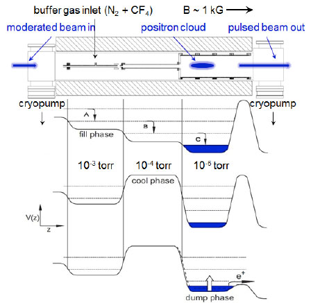
Shown schematically at the right, the three-stage BGT uses a stepped potential well and three regions of successively lower buffer-gas pressure for position accumulation. Positrons are trapped initially in the high-pressure region by excitation of the a1∏ electronic state of N2, then this is repeated twice more to trap them in a low-pressure region (~ 10-6 torr) in which the annihilation lifetime is approximately 100 s. The a1∏ state is unusual in that it lies below the threshold for positronium formation, which is a virulent loss process. Trap efficiency can be as great as 50% using a tungsten moderator and 30% using a (more efficient) solid neon moderator. The neon moderator was added in 1997; and in 2001, CF4 was added to the N2 for faster cooling. Many current devices incorporate rotating-wall electrodes to compress the plasma radially; and for simplicity, some traps use only two stages. The BGT was sold commercially (2002 - 2014) by First Point Scientific, Inc., Agoura Hills, CA. The pulsed beam generated by the BGT in our lab has a total energy resolution as low as 35 meV FWHM, which represented the highest energy resolution positron beam produced at the time, and it is now used as input to the recently developed cryogenic beam-tailoring trap (CBT).
Further Reading:
A Buffer-Gas Trap for the NEPOMUC Positron Beam: Optimization Studies with Electrons, A. Deller, et al., J. Plasma Phys. 935890501, 2023.
Energy distribution and adiabatic guiding of a solid-neon-moderated positron beam, S. Ghosh, et al., J. Phys. B, 53, 085701 (2020).
Non-neutral plasma manipulation techniques in development of a high-capacity positron trap, M. Singer, et al., Rev. Sci. lnstrum. 92, 123504 (2021).
A Buffer-Gas Trap for the NEPOMUC Positron Beam: Optimization Studies with Electrons, A. Deller, et al., J. Plasma Phys., submitted (2023).
Energy distribution and adiabatic guiding of a solid-neon-moderated positron beam, S. Ghosh, et al., J. Phys. B, 53, 085701 (2020).
Positron Trapping in an Electrostatic Well by Inelastic Collisions with Nitrogen Molecules, T. J. Murphy and C. M. Surko,Phys. Rev. A46, pp. 5696-5705 (1992).
The Positron Trap - A New Tool for Plasma Physics, C. M. Surko, et al., Positron Studies of Solids, Surfaces, and Atoms, A. P. Mills, et al. eds. (World Scientific, 1984), p. 222-233.
Excitation of Electronic States of Ar, H2, and N2 by Positron Impact, J. P. Sullivan, et al., Phys. Rev. Lett. 87, 073201-073204 (2001).
Systematic Comparison of Positron and Electron Impact Ionization of the n3 vibrational mode of CF4, J. P. Marler and C. M. Surko, Phys. Rev. A 72, 062702 (2005).
Excitation of Molecular Vibrations by Positron Impact, J. Sullivan, et al., Phys. Rev. Lett. 86, 1494-1497 (2001).
Solid neon moderator for positron trapping experiments, R. G. Greaves, et al., Can. J. Phys. 51, 445-448 (1996).

Cryogenic Beam-Tailoring Trap
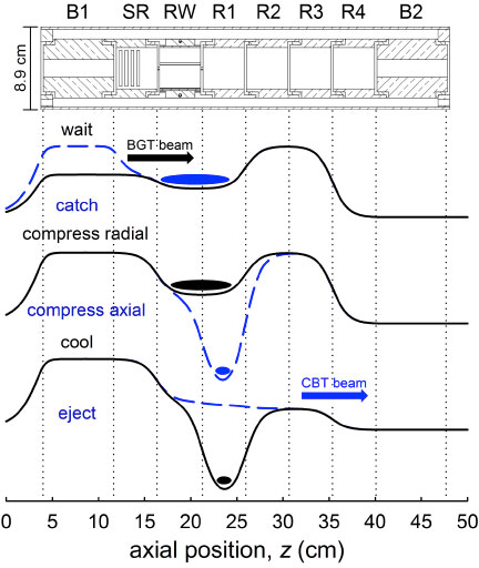
The cryogenic beam-tailoring trap (CBT) was developed in our group by Mike Natisin, James Danielson and Cliff Surko in 2014. It takes a pulsed beam as input and outputs a tailored pulsed beam with superior beam characteristics. Positrons are cooled to 50K through interactions with a cryogenic buffer gas, compressed axially and radially, and ejected as a pulsed cryogenic beam with five times better energy resolution compared with the previous state-of-the-art positron beam.
The CBT consists of 8 cylindrically symmetric electrodes surrounded by a cylindrical shell which are attached via a cold-finger to a high powered cryo-cooler that maintains the electrodes at 50K. Room temperature CO is injected into the region between the outer shell and the electrodes where it cools to 50K through collisions with the cold surfaces, after which it makes its way through a slotted electrode and into the inner cavity where it is able to interact with the trapped positrons.
The CBT consists of 8 cylindrically symmetric electrodes surrounded by a cylindrical shell which are attached via a cold-finger to a high powered cryo-cooler that maintains the electrodes at 50K. Room temperature CO is injected into the region between the outer shell and the electrodes where it cools to 50K through collisions with the cold surfaces, after which it makes its way through a slotted electrode and into the inner cavity where it is able to interact with the trapped positrons.
The CBT operates in six phases, as shown to the right. First it re-traps the pulsed positron beam generated by the buffer-gas Trap (BGT), then subsequently compresses the positrons radially using the rotating wall technique and axially by pulling them into a deep potential well. The positrons are then cooled to 50K through vibrational and rotational excitation of the cryogenic CO buffer-gas and ejected from the trap as a pulsed cryogenic beam.
Using this technique positrons have been successfully cooled to 50K through interactions with either a CO or N2 cryogenic buffer-gas. The resulting beam has a total energy spread of 6.9 meV FWHM, which is a factor of five better than any previous technique, while maintaining sub-microsecond temporal resolution and mm spatial resolution.
Further Reading:
An Ultra-High Energy Resolution Cryogenic Trap-Based Positron Beam, M. R. Natisin et. al., Appl. Phys. Lett. 108, 024102 (2016).
Formation mechanisms and optimization of trap-based positron beams, M. R. Natisin, J. R. Danielson, and C. M. Surko, Phys. Plasmas 23, 023505 (2016).
Formation of buffer-gas-trap based positron beams, M. Natisin et. al., Phys. Plasmas 22, 033501 (2015)
High-field Beam-Tailoring Trap
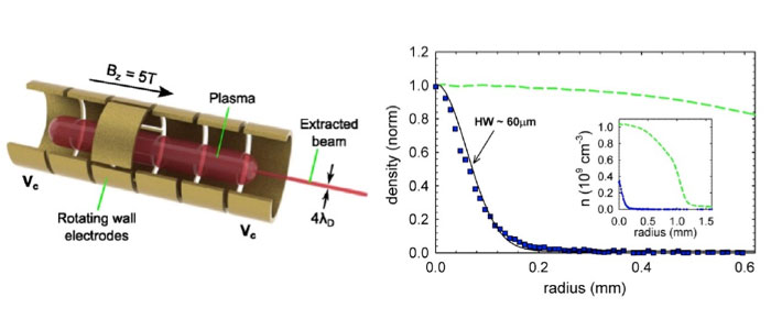
In order to improve plasma lifetimes and create novel beams, a Penning-Malmberg trap was constructed that featured a 5 T superconducting magnet and a cryogenic electrode structure (T ~ 70K). The goal was to produce large (N ~ 1010), high-density positron plasmas and cold positron beams (Δε < 10 mev). with background pressures in the 10-11 torr range and rotating electric fields to counteract plasma expansion from background asymmetries, this trap is designed to be a nearly ideal reservoir of positrons with very long confinement and annihilation times.
This trap uses a warm bore superconducting magnet and a two stage pulse-tube cryogenic refrigerator that is designed to cool the electrodes to < 70 K inside a thermal shield. The electrodes (radii of 1.27 cm) include two that are segmented azimuthally (one 4 sector, and one 8 sector) for the application of transverse electric fields. Plasma density is measured by dumping the plasma onto a phosphor screen and imaging it with a CCD camera. A thermionic electron gun is used to fill the trap with electrons for test experiments.
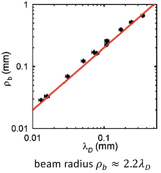
This trap was used for the experiments that discovered the “strong-drive” regime of rotating wall radial plasma compression, the creation and study of micro-beams, the development of the diocotron autoresonace manipulation technique, and many other steps towards the development of a multicell trap for the long-term storage of large numbers of positrons.
Further Reading:
Multi-cell trap developments towards the accumulation and confinement of large quantities of positrons, M. Singer, et al., J. Plasma Phys. 89, 935890501 (2023).
Tailored Particle Beams from Single-Component Plasmas, T. J. Weber et al., Non-Neutral Plasma Physics VII, AIP Conf Proc. 1114, 171 (2009).
A Cryogenic, High-field Trap for Large Positron Plasmas and Cold Beams, J. R. Danielson et al., Non-Neutral Plasma Physics V, AIP Conf Proc. 692, 149 (2009).
Radial Compression and Torque-balanced Steady States of Single-Component Plasmas, J. R. Danielson and C. M. Surko, Phys. Plasmas 13, 055706 (2006).
Torque-balanced High-density Steady States of Single Component Plasmas, J. R. Danielson and C. M. Surko, Phys. Rev. Lett. 95, pp. 035001-4 (2005).
Multi-Cell Trap Development
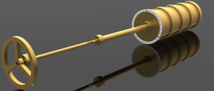
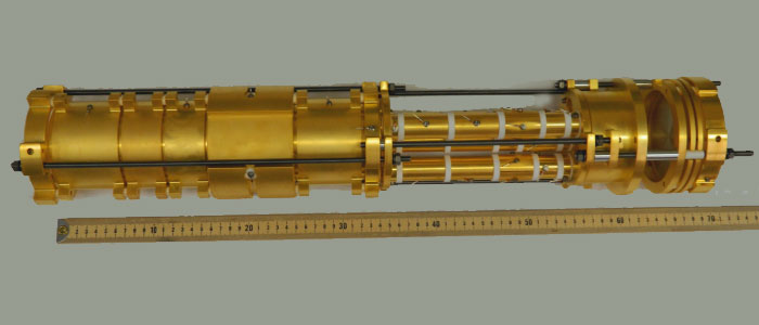
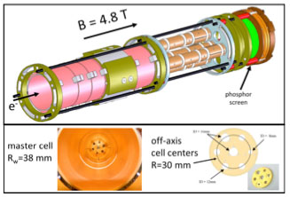
The multicell positron trap consists of a three-dimensional array of Penning-Malmberg traps for accumulation and storage of large numbers of positrons. We have recently conducted experiments with electron plasmas in the test structure shown at the left to establish the feasibility of key features of the design.
The test structure, pictured above and at the right, consists of a master cell and four storage cells, one on, and three off of the magnetic axis. Each cell includes a segmented electrode that enables radial plasma compression using the “rotating wall” technique. A large phosphor screen is used to image plasmas in the storage cells. The goals and accomplishments thus far are:
- Efficient injection into off-axis cells (≥ 95 %) has been established.
- Trapping in off-axis cells has been verified.
- Operation and stability for kV space charge potentials remains to be tested.
- Optimal lengths and radii of the storage cells remains to be determined.
Fulfillment of the remaining requirements is expected to enable the construction of a trap with ~ 20 cells capable of storing 1012 positrons using kV confinement potentials.
Further Reading:
Multi-cell trap developments towards the accumulation and confinement of large quantities of positrons, M. Singer, et al., J. Plasma Phys. 89, 935890501 (2023).
Magnetic field considerations for a multi-cell Penning-Malmberg trap for positrons, D. Witteman, et al., J. Plasma Phys. 89, 935890405 (2023).
Confinement and manipulation of electron plasmas in a multicell trap, N. Hurst, et al., Phys. Plasmas 26, 013513 (2019).
Progress Towards a Practical Multicell Positron Trap, J. R. Danielson et al., Non-Neutral Plasma Physics VIII, AIP Conf Proc. 1521, 101 (2013).
Electron Plasma Dynamics During Autoresonant Excitation of the Diocotron Mode, C. Baker et al., Phys. Plasmas 22, 022302 (2015).
Electron Plasma Orbits from Competing Diocotron Drifts, N. C. Hurst et al., Phys. Rev. Lett. 113, 025004 (2014).
Plasma manipulation techniques for positron storage in a multicell trap, J. R. Danielson et al., Phys. Plasmas 13, 123502 (2006).
A Multicell Trap to Confine Large Numbers of Positrons, C. M. Surko and R. G. Greaves, Radiation Physics and Chemistry 68, pp. 419-425 (2003).
8-Segment Trap (8ST)
We have built a modified electron plasma trap specifically for conducting studies of vorticity dynamics. It features a confinement region with a segmented electrode (divided into 8 segments) spanning the entire length of the confinement region. This allows us to use the boundary conditions to impose external ExB flows which advect the electron density, which is analogous to fluid vorticity.
Thanks to a mathematical isomorphism between the equations governing electron plasma behavior and those governing ideal fluid in two dimensions, electron plasmas can be used to study vorticity dynamics in a way that provides distinct advantages over traditional fluid experiments. In particular, we are studying the behavior of a coherent vortex in response to various types of externally imposed flows. In order to impose such flows, we apply voltages to an azimuthally segmented electrode.
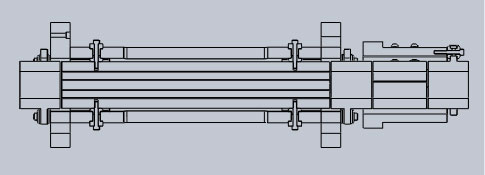
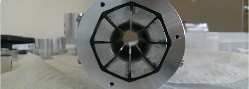
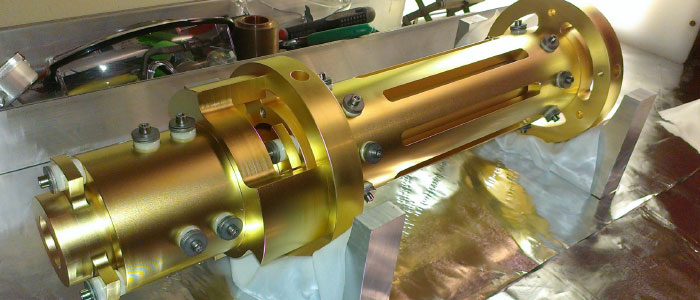
Previous experiments conducted in the Multi-Cell Test Structure suffered from the fact that the segmented electrode spanned only a fraction of the plasma length, thus contributing 3-dimensional effects and invalidating the plasma/fluid isomorphism. The 8-Segment Trap circumvents this problem by extending the segmented electrode over the entire length of the plasma, allowing for pure 2D dynamics. Shown to the right are a cutaway technical drawing of the 8ST (top) and a view of the 8–segmented electrode prior to gold-plating.
Further Reading:
Inviscid damping of an elliptical vortex subject to an external strain, P. Wongwaitayakornkul, et al., Phys. Plasmas 29, 052107 (2022).
“An electron plasma experiment to study vortex dynamics subject to externally imposed flows,” N. Hurst et al., AIP Conf. Proc., 1928, 020007 (American Institute of Physics, 2018).
Evolution of a Vortex in a Strain Flow, N. C. Hurst, J. R. Danielson, D. H. E. Dubin and C. M. Surko, Phys. Rev. Lett. 117, 235001 (2016).
Experimental study of the stability and dynamics of a two-dimensional ideal vortex under external strain, N. C. Hurst, J. R. Danielson, D. H. E. Dubin and C. M. Surko, J. Fluid Mech. 848, pp. 256 – 287 (2018).